
Contact-Adaptive Robotic Ultrasound Probe Control for Tissue Exploration and Continuous Task-Relevant Visualization Using Robot-Free Image–Motion Demonstration
While a clinician performs the primary procedure, a robotic assistant can hold the view the clinician chose so that changing tissue stays observable. Sonologger clamps a six-axis IMU to the clinician-operated probe and records synchronized ultrasound and probe rotation with no robot, camera or tracker; rather than imitating trajectories, the recordings measure which probe axis and sign the clinician uses to correct an image offset. Those measurements parameterize an interpretable, non-learned controller, which acquired and held a task-relevant view in 7 of 7 blind poses on a dynamic bladder phantom against 1 of 7 for a static hold.
Most robotic ultrasound aims at a standardized view: press along a planned trajectory, servo toward a standard plane, reproduce an expert sweep. The role considered here is different. While a clinician performs the primary procedure, a robotic assistant holds a view the clinician has chosen, so that tissue which is changing stays observable. The decisions that follow from the view remain the clinician's; the robot is a probe holder that keeps the picture.
That is hard because tissue geometry and probe contact change together. It is also hard to collect demonstrations for, because learning from demonstration normally assumes the demonstration was recorded on the learner — which means putting a robot next to the patient before you have anything to put there.
Recording the clinician instead of the robot
Sonologger clamps a six-axis inertial unit to the clinician's own probe and logs ultrasound and probe-frame rotation on one laptop clock. No robot, no camera, no optical tracker — the whole addition is a clamp, a sensor and a laptop.
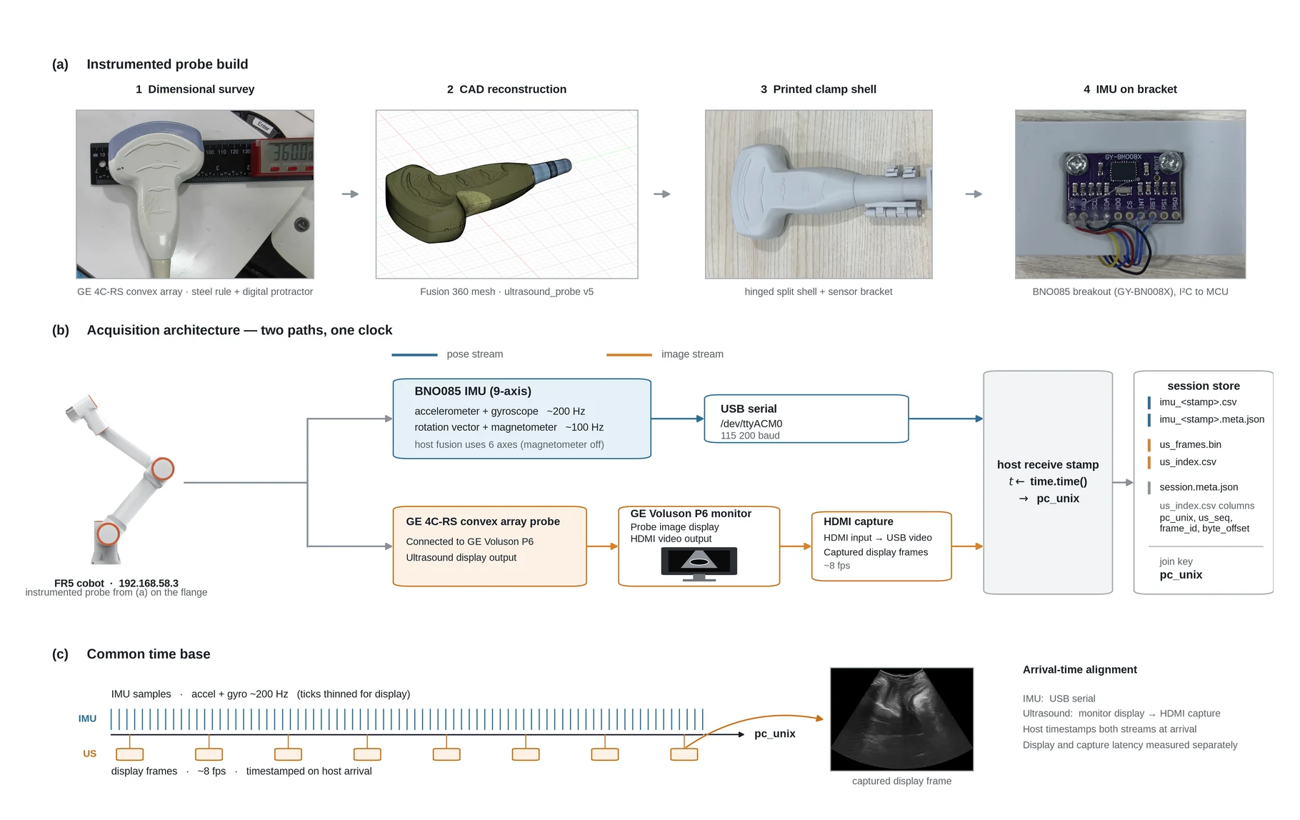
Two streams at different rates need their offset measured, not assumed. The effective ultrasound delay is estimated by maximizing the correlation between frame-to-frame image change and the time-shifted gyroscope magnitude; it peaks at 200 ms pooled over 226 sessions, and is removed once during dataset construction. Still–move–still segmentation then cuts the recording at low-motion brackets, and each accepted interval yields a relative-rotation label with the 20 preceding frames. Two days of scanning by one operator produced 268 sessions, 45,902 frames, 1,818 move segments and 4,389 chunks.
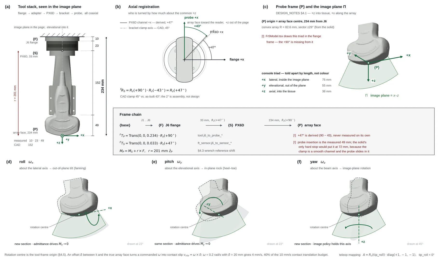
Each move is represented in the probe frame by
which removes the unobservable global heading of a six-axis filter and keeps the axes consistent across moves.
The measurement scope is stated rather than assumed. Against FR5 kinematics on the same 84 s teleoperated recording, magnetometer-free fusion gives 2.52° geodesic RMS and 0.23°/min drift, while the on-chip nine-axis rotation vector degrades badly near the steel arm. Translation is recorded and never used.
| Configuration | RMS / 95th pct. | Drift | Role in the controller |
|---|---|---|---|
| Six-axis fusion, no magnetometer | 2.52° / 3.61° | 0.23 °/min | Used, for short relative rotations |
| Nine-axis on-chip rotation vector | 12.55° / 18.91° | 8.29 °/min | Rejected: magnetic distortion near the robot |
| IMU translation integration | 6.3 mm at 5 s | accumulating | Recorded, excluded from control |
What the demonstrations actually say
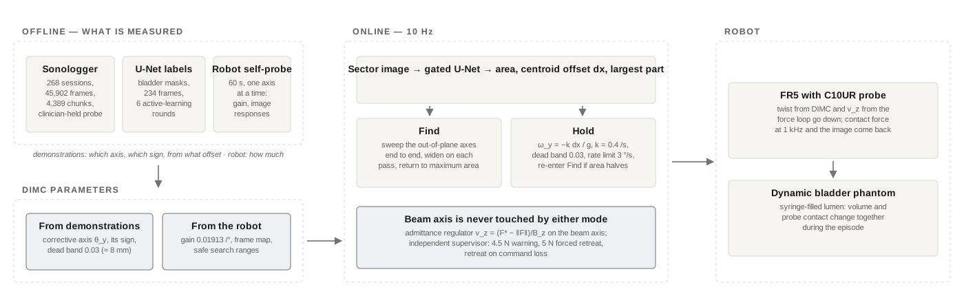
The recordings are not trajectories to imitate. They are read for one thing: which probe axis the clinician turns when the structure drifts off-centre, in which direction, and from what offset. Across the target-present chunks, the lateral centroid offset correlates only with the in-plane rotation (Spearman , ), not with out-of-plane or beam-axis rotation. The fraction of moves that are corrective rises from near chance inside a small-offset region to 91.6% at large offsets — and the edge of that region is where the dead band goes, at 0.03 (about 8 mm).
So the demonstrations fix the axis, the sign and the threshold; the robot's own 60 s self-probe fixes the gain magnitude (0.01913 /°) and the image response of each axis. The two agree on the corrective sign but not its magnitude, which is exactly the split the design assumes: human data for the behaviour, robot data for the plant.
DIMC is therefore interpretable and not learned. Find sweeps the out-of-plane axes end to end when the structure is not visible — a sweep rather than hill climbing, because the area of an unseen structure is zero and has no gradient — and returns to the pose of maximum mask area. Hold centres with at s⁻¹ inside a 3 °/s rate limit, and falls back to Find if the area drops below half its best value.
Contact, and the supervisor that does not trust the controller
The beam axis is never touched by either mode; it belongs to an admittance regulator, . The target force is not a fixed 3 N but the lowest safe force with near-best image quality,
with a noise-aware . An independent supervisor blocks rising commands above 4.5 N, commands a retreat at 5 N, and retreats on command loss.
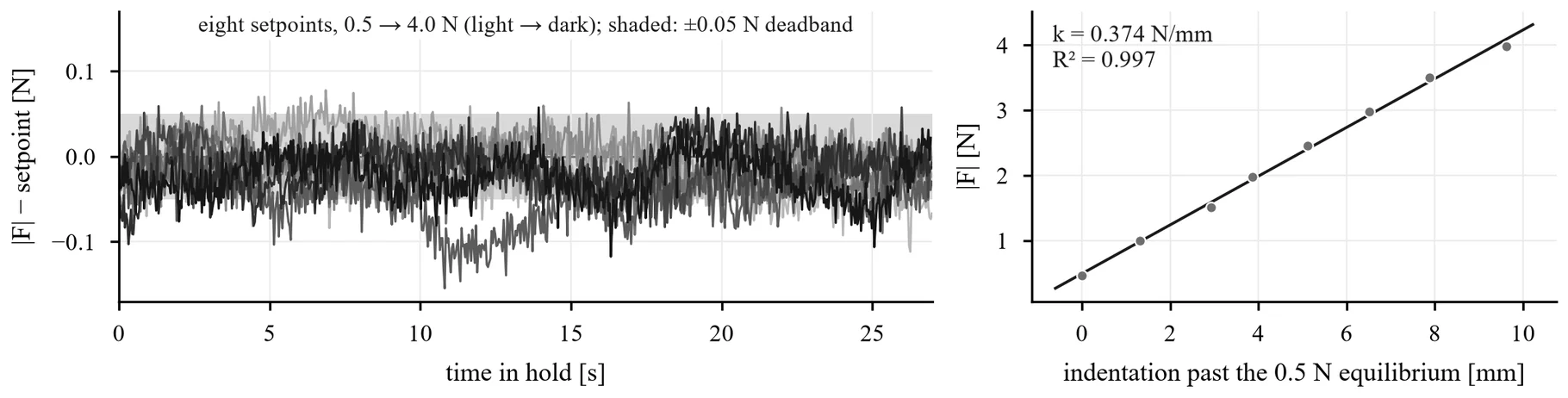
| Target [N] | SD [N] | Mean error [N] | In band [%] | Peak [N] |
|---|---|---|---|---|
| 0.5 | 0.023 | −0.017 | 88.9 | 0.60 |
| 1.0 | 0.022 | −0.013 | 83.9 | 1.10 |
| 1.5 | 0.022 | −0.012 | 94.1 | 1.57 |
| 2.0 | 0.026 | −0.016 | 89.9 | 2.09 |
| 2.5 | 0.029 | −0.031 | 72.9 | 2.59 |
| 3.0 | 0.026 | −0.015 | 89.7 | 3.10 |
| 3.5 | 0.025 | −0.008 | 93.7 | 3.59 |
| 4.0 | 0.049 | −0.025 | 82.9 | 4.36 |
Under syringe-induced surface displacement the loop does not reduce the peak of an injection (0.83 N against 0.74 N with the loop off) — that peak is set by how fast the surface rises against the 12 s time constant — but it changes everything after it: probe travel of 0.13 mm per event against 0.005 mm, and post-peak return rate rising from 0.13 to 0.23 N/s (, 70 events per arm). The supervisor was exercised rather than assumed: at the 4.0 N set point four of five injections drove the force past 5 N, the retreat fired each time, and the force was back below the 4.5 N warning within 1.0–1.4 s.
The blind test
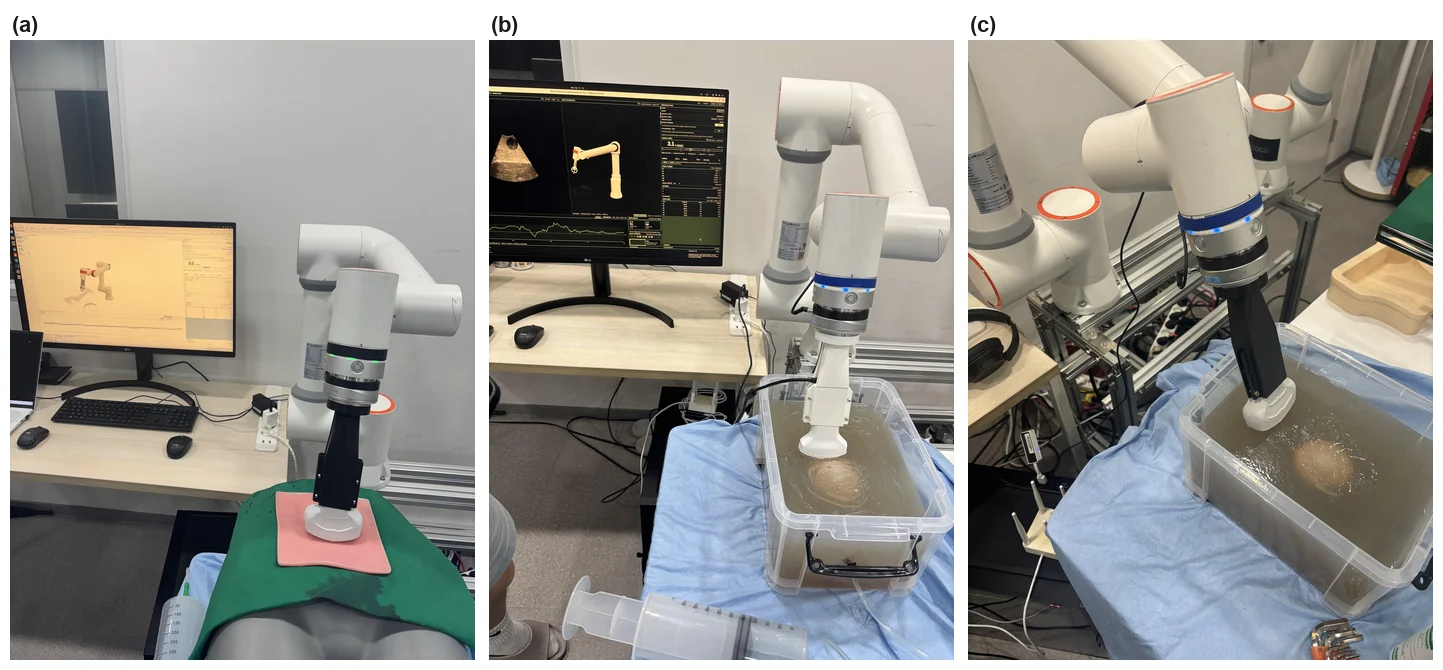
Seven randomized, operator-blinded starting poses on the dynamic phantom, 120 s of closed-loop control each, DIMC against a static hold on the same force and safety stack. Success is a task-relevant view held for 3 s under criteria frozen before the test, and the analysis is pose-paired.
| Pose | DIMC [s] | Static hold [s] |
|---|---|---|
| 1 | 50.7 | no |
| 2 | 10.9 | 35.4 |
| 3 | 13.0 | no |
| 4 | 7.8 | no |
| 5 | 25.4 | no |
| 6 | 16.4 | no |
| 7 | 9.3 | no |
| Found | 7 / 7 | 1 / 7 |
DIMC found and held the view in 7 of 7 poses against 1 of 7 for the static hold; all six discordant pairs favour DIMC (McNemar exact ). The single static-hold success started with the lumen already visible. First view came after a median of 13.0 s, and was then held for 73–112 s of the remaining episode.
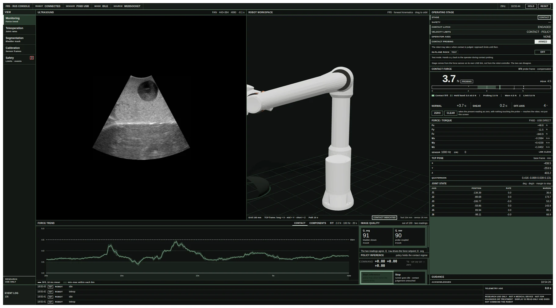
During pose 1, syringe filling and withdrawal changed lumen volume and probe contact while the episode ran. DIMC retained the view through the disturbance and through a supervisor retreat — force peaked at 5.07 N while the mask stayed above the task threshold — whereas the static hold stayed below the limit (peak 4.77 N) but had no way to re-centre the image.
Limitations
This is a single-operator phantom study. No patient data, no clinical deployment, no absolute translation and no global trajectory are claimed, and "contact-adaptive monitoring" names the intended systems role rather than a validated clinical capability. The bench is deliberately faster than the task — the syringe delivers 500 mL in a few seconds, whereas an organ under irrigation changes over tens of seconds to minutes. Session-wise splits assess reproducibility, not generalization across operators or anatomy.
Code and the main-test records are at suung23/FR5-for-RUS.