
Contact-Stable Deformable Tissue Simulation Using Implicit Integration and Live-Pose Grasp Constraints for Laparoscopic Surgery Robot Policy Evaluation
Closed-loop evaluation of surgical robots needs tissue that deforms, can be grasped and lifted, and reproduces the anatomy the robot will work in. We reconstruct that tissue from a single fixed-view RGB-D recording of the surgical field — composited to remove the instruments, closed into watertight volumes and tetrahedralised — and place it in a bimanual cell where two Franka FR3 arms work through 6 mm trocars. The contribution is the numerical and contact design that keeps that cell stable: implicit integration, simulation meshes separate from collision meshes, numerical guards, and a grasp constraint captured at the live tissue pose.
Screening a surgical policy before it touches an animal requires an environment whose organs deform, can be grasped and lifted, and are arranged as in the field where the demonstrations were recorded. Neither a hand-authored scene nor a CT-derived model reproduces that arrangement. We therefore converted a recording that already existed — a RealSense D405 looking down at the surgical field during ex-vivo data collection — into simulable tissue.
The reconstruction turned out to be the smaller part of the work. A tetrahedral mesh extracted from a marching-cubes surface is not yet a soft body that two robot arms can grasp through trocars: at the element size of this anatomy non-implicit integrators diverge, voxel resolution changes bending stiffness independently of the material, a shared simulation and collision mesh leaves the organ static, and a naive grasp constraint pushes the instrument out of its port. What follows is mostly about those four problems.

One viewpoint, closed into a volume
Because the camera is fixed, pixel observes the same ray in every frame, so frames combine by indexing rather than registration. Instruments are removed by taking the per-pixel median over a window in which the pixel is neither masked as instrument nor invalid; a ±90-frame window at stride 2 recovered 3.4% of the image under the instrument mask and raised usable depth coverage to 90.3%. Organs are segmented with SAM 2.1 from point prompts.
FEM needs a closed volume, and one viewpoint measures only the front surface. With the metric distance from an interior pixel to the silhouette and , the back surface is modelled as a rounded cap,
after which occupancy is marked on a 1.5 mm grid, closed morphologically, surfaced by marching cubes, Taubin-smoothed and tetrahedralised with TetGen. Every element's signed volume is checked and inverted elements are reoriented.
The same path was run unchanged on three specimens of two species. All thirteen organs came out watertight with no inverted tetrahedra, across a 1400-fold range of organ volume.
| Scene | Organs | Nodes | Tets |
|---|---|---|---|
| A — rabbit, used in the robotic cell | 6 | 11,962 | 43,956 |
| B — second rabbit | 5 | 7,893 | 29,224 |
| C — porcine liver and gallbladder | 2 | 18,665 | 72,881 |
| Total | 13 | 38,520 | 146,061 |
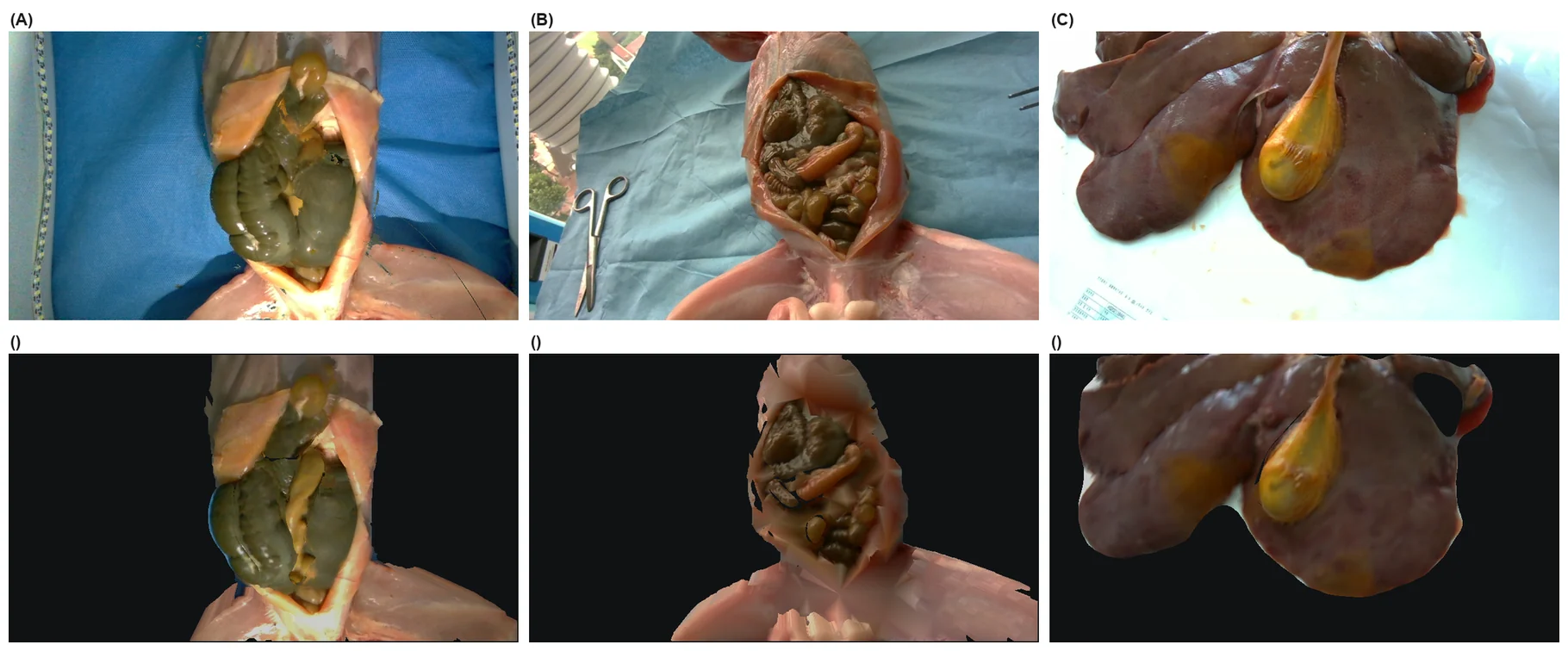
Measured against the depth map it was built from, the rabbit front surface is accurate to 1.33–1.41 mm — close to the 1 mm depth quantisation plus half a voxel. The porcine liver, the largest and flattest structure, is worse at 4.77 mm. The signed error is negative on all four organs, consistent with marching cubes placing the surface half a cell beyond the occupied cells.
The solver has to be implicit
Each organ is an isotropic hyperelastic solid over its tetrahedra, with Green strain and energy density
with and moduli taken from the literature rather than identified from the recording.
At a median element edge of about 1.6 mm, a stable explicit step would need s. Both non-implicit alternatives we tested — semi-implicit integration and XPBD — reach the scene's particle velocity limit on the first frame and stay there, and neither more substeps nor a uniform mass distribution changed that, which points at element size rather than mass ratio. We therefore integrate with Vertex Block Descent, which recasts one implicit Euler step as
and minimises it by block coordinate descent, one Newton step per vertex, graph-coloured so that same-colour blocks update in parallel. At s with 8 substeps of 10 iterations, free fall matches the analytic solution to four significant digits and the scene stays at 0.16 m/s where the other two integrators sit at the 20 m/s clamp.
Two discretisation details mattered as much as the integrator. Voxelisation adds stiffness unrelated to the material: at the automatic resolution the appendix received 154 nodes and, spanned by a few large hexahedra, could not drape over the jaws at any modulus, so the resolution is fixed at 16 cells along each organ's longest axis. And a hexahedral simulation mesh cannot double as the collision mesh — cooking fails silently, and the organ renders and skins but never moves. Over one second an isolated cube in that configuration moved 0.00 mm while every other configuration fell about 4.9 m.
The grasp is the hard part
Friction is not enough for tissue of a few kilopascals. With the grasp assist disabled, 0 of 15 repeated grasp-lifts held the appendix: the tissue rose 4.9 mm for 15 mm of jaw lift and slipped 10.1 mm. Raising the modulus until friction holds would misrepresent the organ in every other interaction, so the grasp is instead a kinematic constraint on a subset of tissue nodes.
Where that constraint is captured turns out to decide whether the cell stays inside its ports. Let be the step at which the jaws close on in-mouth tissue, the jaw frame and the cluster nodes. Offsets captured from the live tissue,
give a constraint whose residual at activation is zero by construction. An attachment authored at the rest pose instead imposes, in a single step,
which is exactly the displacement of the organ since rest. After a scripted approach mm, and the FEM reaction to it displaced the instrument 13 mm out of its 6 mm port.
| Grasp design | Held | Diverged | Lift (mm) | Slip (mm) | Snap (mm) |
|---|---|---|---|---|---|
| Friction only | 0/15 | 0/15 | 4.9 | 10.1 | — |
| Rest-pose constraint | 13/15 | 1/15 | 15.1 | 0.45 | 4.7 |
| Live-pose constraint | 13/15 | 2/15 | 15.2 | 0.32 | 0 |
| Re-grasp, rest-pose | 5/5 | 0/5 | 15.4 | 0.48 | 4.3–17.8 |
| Re-grasp, live-pose | 5/5 | 0/5 | 15.2 | 0.37 | 0 |
Medians over five grip locations and three approach offsets. Held: the tissue follows at least 80% of the jaw lift with less than 3 mm of slip.
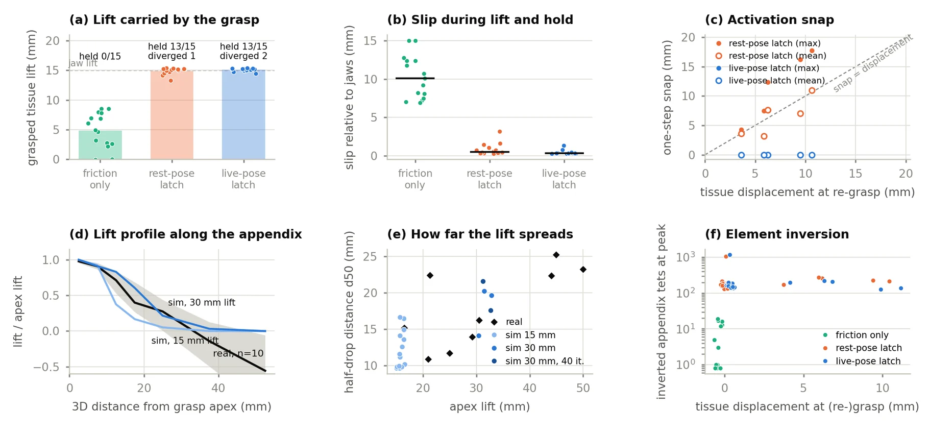
Isolating the effect: the jaws grasped tissue, dragged it 5 or 10 mm, released and closed again. At re-grasp the tissue sat 3.6–10.6 mm from rest, and rest-pose attachment produced one-step snaps of 4.3–17.8 mm, the node-mean snap proportional to displacement (slope 0.91, ). Live-pose capture produced no snap at all. In the articulated PhysX cell the same mechanism drove the RCM error to 16.4 mm with 6 of 60 control steps beyond 3 mm — and to 0 of 60 after the change.
Two arms, two backends, one contract
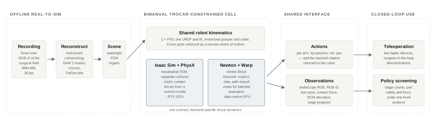
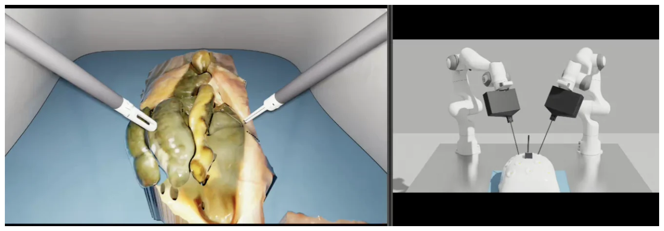
Two FR3 bases stand 0.900 m apart with a 0.46 m stand-off, the left arm carrying a motorised grasper and the right a motorised cutter, each through a 6 mm port. Because the shaft must pass through that port, tip pitch and yaw follow from tip position: each arm has four commandable degrees of freedom plus the jaw, and the interface returns any rejected rotation to the caller.
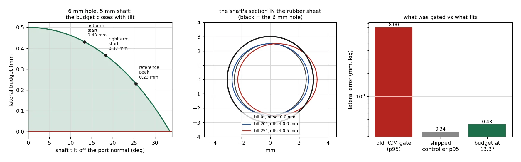
The port is the tightest tolerance in the cell. A 5 mm shaft in a 6 mm hole has 0.5 mm of lateral clearance at normal incidence, falling to zero at about 34°; at the start pose the arms are tilted 13.3° and 18.3°, leaving 0.43 and 0.37 mm. The controller, chosen by a 182-configuration grid search, holds the 95th-percentile deviation at 0.34 mm and tracks free motion with 0.048 mm RMS error.
Both backends run under the same contract: arm motion is identical and only tissue deformation may differ. Backend A is Isaac Sim 5.1 with PhysX FEM on an RTX 4090; backend B is Newton (Warp) with VBD and a path tracer that needs no RT cores, for batched evaluation. The second backend parses the cell constants out of the first one's build script, so the two cannot drift apart.
What it matches, and what it does not
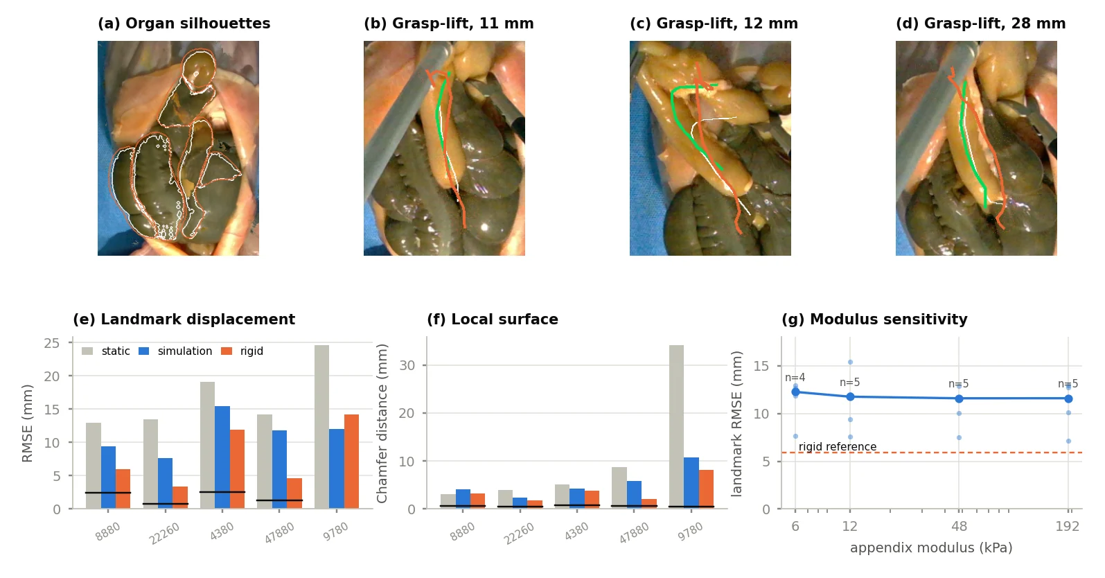
Projected through the pose of the recording camera, the simulated rest scene reaches a mean organ silhouette IoU of 0.80. Projected through the cell's own D405 model — 7.9 mm off laterally, 4.6 mm vertically, different intrinsics — the same scene gives 0.24, which is a useful reminder of how much of a real-to-sim number is the camera.
Six real grasp-lifts with grasp-point displacements of 11–38 mm were reproduced in simulation by aligning the pre-grasp centreline to the simulated rest centreline and moving the cluster at the same arc length by the measured displacement.
| Metric | Simulation | Reference |
|---|---|---|
| Depth error (mm) | 1.33–1.41 | 1.0 quantisation |
| Silhouette IoU | 0.80 | 0.24 from the cell camera |
| SSIM / PSNR (dB) | 0.63 / 20.4 | 0.67 / 19.5 real; 0.66 / 19.0 mean |
| Landmark RMSE (mm) | 11.8 | 14.2 static; 5.9 rigid; 2.4 floor |
| Local Chamfer (mm) | 4.3 | 5.1 static; 3.2 rigid; 0.6 floor |
The simulated landmark displacement RMSE of 11.8 mm sits below the static prediction and above the rigid one, and the local Chamfer distance follows the same order: the simulated appendix deforms more locally around the grasp than the real one does. Sweeping the appendix modulus from 6 to 192 kPa moved the median RMSE only from 12.3 to 11.6 mm, so stiffness is not the explanation; the unobserved distal fixation and support of the appendix are the remaining candidates. For the same reason, agreement in lift spread does not identify a modulus, and we do not claim biofidelity.
Throughput, and what the environment is for
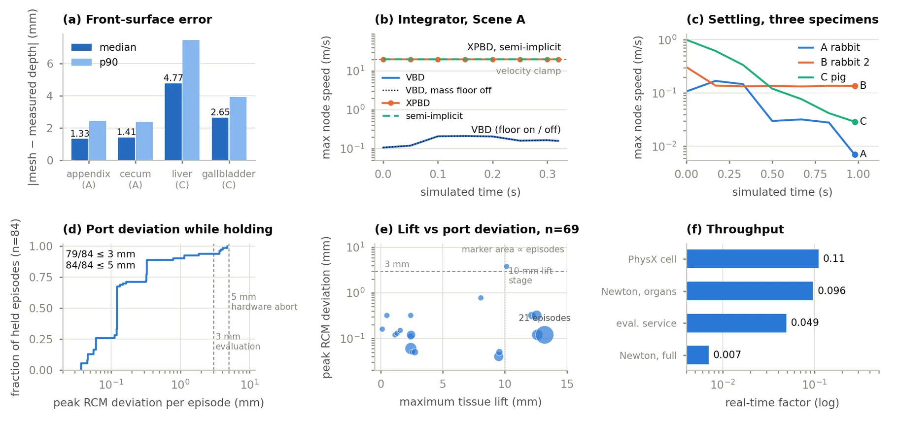
Neither backend runs in real time. The PhysX cell advances an eight-step, 30 Hz action chunk in about 2.4 s with physics at 480 Hz; on an H100, Newton runs the organs alone at 0.096× real time and a full episode with arms and rendering at 0.007×. Under closed-loop load the cell held: of 140 rollouts from six controllers, 84 attached the tissue and 83 held it to the end, with a median peak RCM deviation of 0.12 mm and every episode inside the 5 mm hardware abort threshold.
The environment served as the closed-loop screening stage of a companion policy study, which selected its deployed configuration on port safety and stage-progress counts. Two lessons came out of that use. Binary stage gates need calibration — only 5 of 522 demonstrations closed the cutter below the 0.15 threshold, and rescoring 576 rollouts at thresholds from 0.15 to 0.50 yielded between 0 and 62 passes — so continuous channels are reported next to the gate sweeps. And simulated teleoperation data (1,009 episodes) did not improve real-rig performance when mixed into training, with a crossed ablation attributing most of the gap to appearance. The environment is for screening, not for generating photorealistic training data.
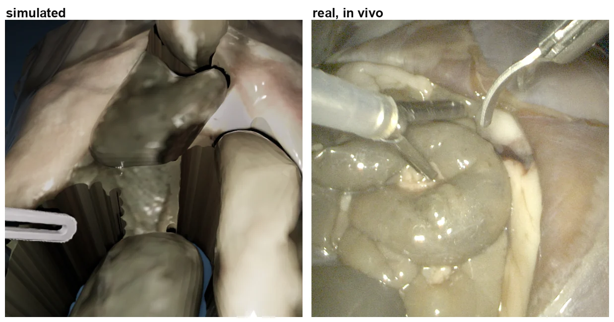
The route needs only a fixed-view capture and a segmentation, so it extends to in-vivo sessions. What comes out is a contact-stable, simulable copy of the observed specimen — not an identified biomechanical model.
Limitations
Moduli are literature values, and neither lift spread nor landmark displacement from video identifies them; force–displacement agreement would need force measurement, and 1 mm depth quantisation limits what small presses can reveal. Only specimen A is used in the robot cell. The grasp is a kinematic constraint that models neither slip nor tearing nor jaw pressure, inverts about 2% of appendix elements at peak lift, and diverges in 30 mm lifts unless the appendix modulus is high enough. Real-to-sim deformation was evaluated on surgeon-performed grasp-lifts rather than robot-executed ones. The environment is neither real-time nor run-to-run deterministic.