
Drape-Compatible Tool-Tip Localization for Hand-Held Laparoscopic Instruments via UWB Carrier-Phase Ranging and Trocar-Constrained Geometry
A draped instrument hides every optical path on itself, so we estimate the tool tips from distances and an IMU alone. Ultra-wideband carrier phase between nodes on the handle side of the instruments gives three distances; the trocar reduces each instrument to a single insertion depth, leaving one equation to spare that exposes a wrong integer instead of absorbing it. In an 11-hole phantom among metal instruments the three distances hold σ = 0.10–0.33 mm at 35–46 Hz, and a sterile drape pressed onto the antennas leaves the link unchanged.
A surgical robot policy consumes geometry at each timestep: where each instrument's working end sits relative to the camera and to the other instrument. A conventional laparoscopic operation records none of it. Optical trackers need line of sight to markers while the part to be localized is inside the patient; electromagnetic trackers degrade among the metal instruments that fill a surgical field; markerless endoscopic estimation degrades under occlusion. The operating room compounds all three, because an instrument that enters it must be draped unless all of its electronics are sterilized — and the drape seals any optical path on the instrument inside the barrier.
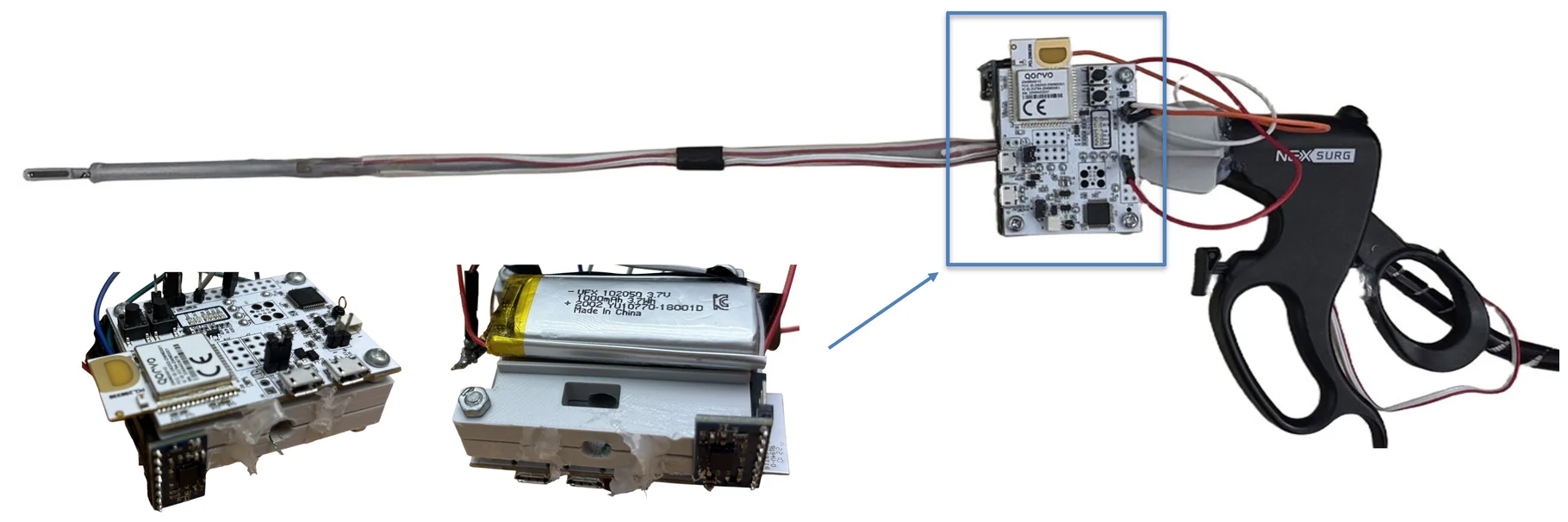
Distance is the one quantity the drape leaves intact. We therefore clip an ultra-wideband node near the handle of each hand-held instrument and one on the endoscope, all outside the sterile barrier, and let them range against each other. Radio crosses the drape, and a distance, unlike a marker or an image, needs no line of sight.
Two problems, one radio and one geometry
The exchange whose pulses give a coarse time of flight also carries the carrier's phase of arrival. At channel 5 one cycle spans 46.2 mm, so a few degrees of phase noise is tens of micrometres of path. Between rounds we accumulate the wrapped phase increment,
which is exact as long as the instrument moves less than mm between rounds — up to 400 mm/s at 35 Hz. Time of flight is not fused into that chain: the antenna delay of these development boards is uncalibrated and its per-boot bias re-randomizes by ±70–100 mm, so ToF only seeds where each episode starts.
That leaves two difficulties. Keeping the phase chain continuous is the radio problem; turning three distances into two tool tips is the geometric one. Three scalar distances cannot place two free-floating instruments — the two instrument antennas carry six coordinates against three measurements — and phase fixes distance only modulo mm, so a lost round slips the registration by a whole cell.
Keeping the chain unbroken
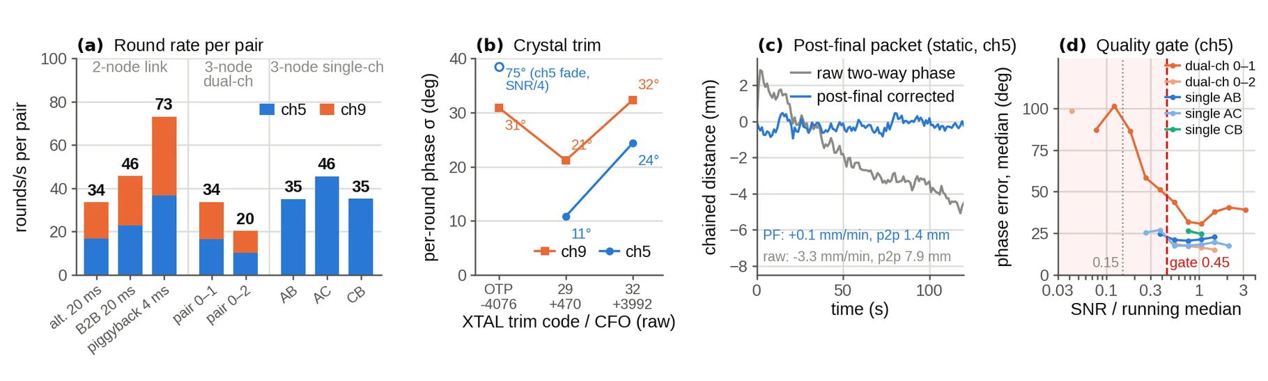
Four mechanisms do the work. A post-final packet measures each round's residual carrier-frequency term, which holds block-mean phase coherence at 0.964 even under a forced PLL re-lock every 2 s (0.885 uncorrected) and suppresses static drift from −3.3 to +0.1 mm/min. Crystal trimming halves per-round phase noise, from 24.3° to 10.8° on channel 5. A per-round quality gate on SNR rejects rounds at multipath amplitude nulls, whose phase is not the path's; fewer than 0.2% of rounds fall below it. And the three nodes stay on one channel: the usual two-channel synthetic wavelength admits near-coincident false fixes, cannot be sampled simultaneously, and re-randomizes the carrier phase at every hop — our two-channel version slipped a cell every 30–60 s.
The three-node single-channel schedule sustained 35.1, 45.5 and 35.2 rounds/s on the three pairs with no failed exchange in 125,176 rounds.
The trocar supplies what distance lacks
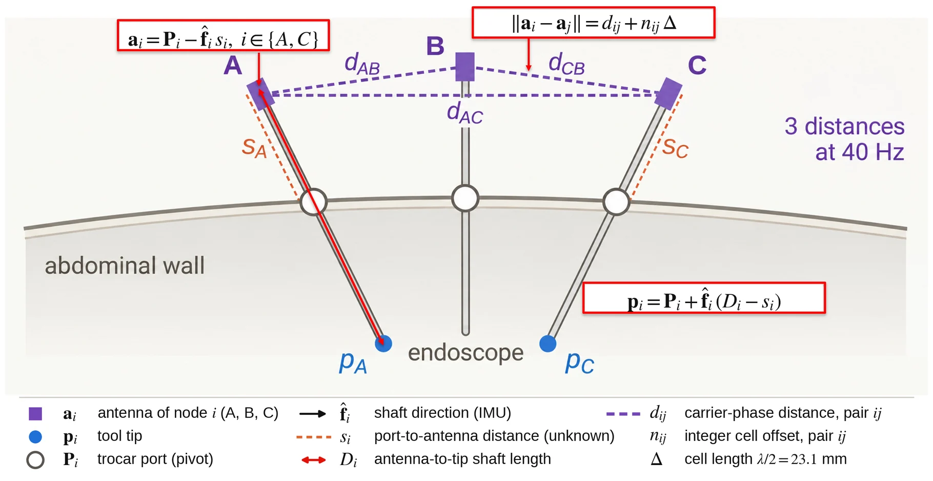
Because the shaft passes through the port, the antenna of instrument lies on the line through the port with direction from the on-board IMU,
and with the antenna-to-tip shaft length the tool tip is . The insertion coordinate is the instrument's only unknown. A two-way carrier-phase observation on pair then reads
so three pairs give three equations in two continuous unknowns and three integers. Unlike the standard treatment of carrier-phase ambiguity, which buys the integer with more measurements, we buy it with kinematics the operating room already provides — and the spare equation is what makes a wrong integer visible instead of absorbed. The integers are enumerated over 31 hypotheses covering ±116 mm, and the arbiter commits a correction only when the residual margin exceeds 3 mm for five consecutive solves.
What the measurements show
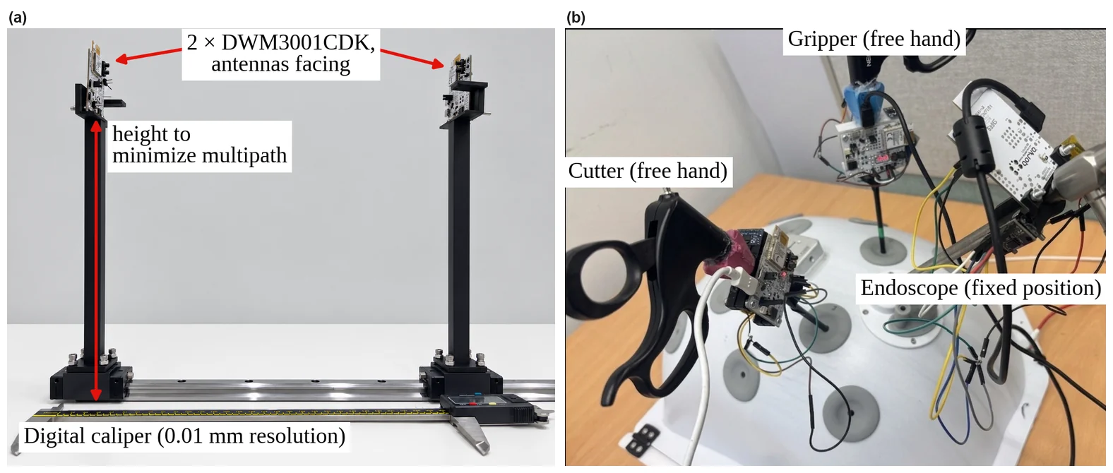
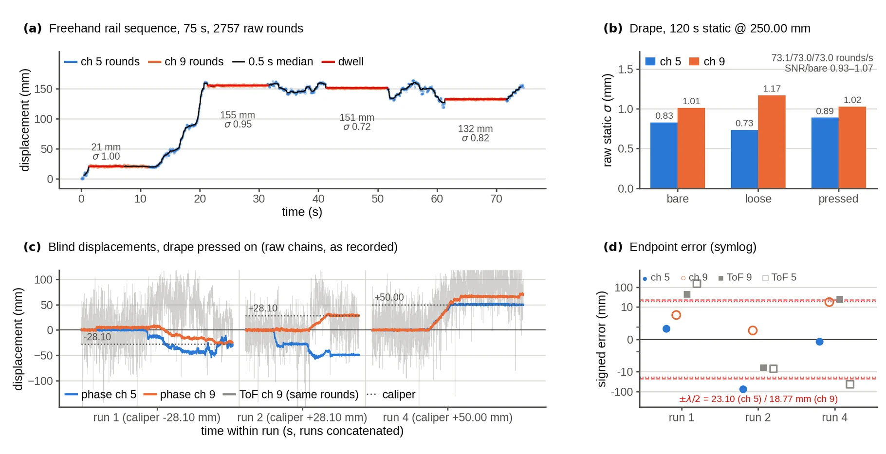
The drape changes nothing. Bare, loosely draped and with the drape pressed onto both chip antennas, the round rate was 73.1, 73.0 and 73.0 rounds/s, first-path SNR stayed within 0.93–1.07 of its bare value, and raw static σ was 0.83/0.73/0.89 mm on channel 5 — the spread follows the channel, not drape contact. With the drape pressed on, three blind displacements were tracked at 0.81 mm mean absolute error, while ToF on the very same rounds erred by 6.7–149 mm.
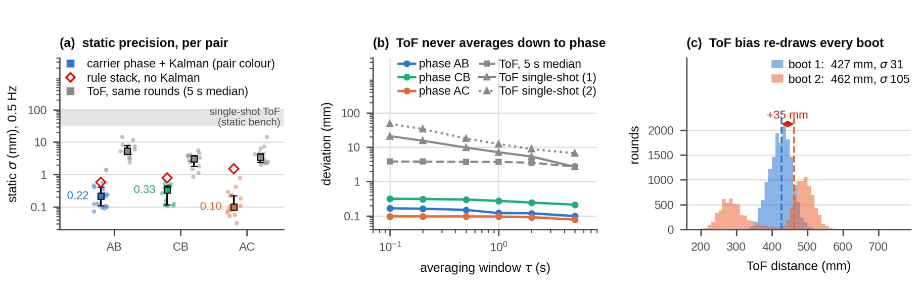
In the 11-hole phantom, among metal instruments and with oblique antennas, the tracked distance held a median σ of 0.22, 0.33 and 0.10 mm on the three pairs. Averaging does not rescue ToF: across two power cycles of the same static bench pair the ToF median moved by 35.2 mm and the single-shot σ grew from 31 to 105 mm. A bias that re-draws at every boot cannot be averaged away.
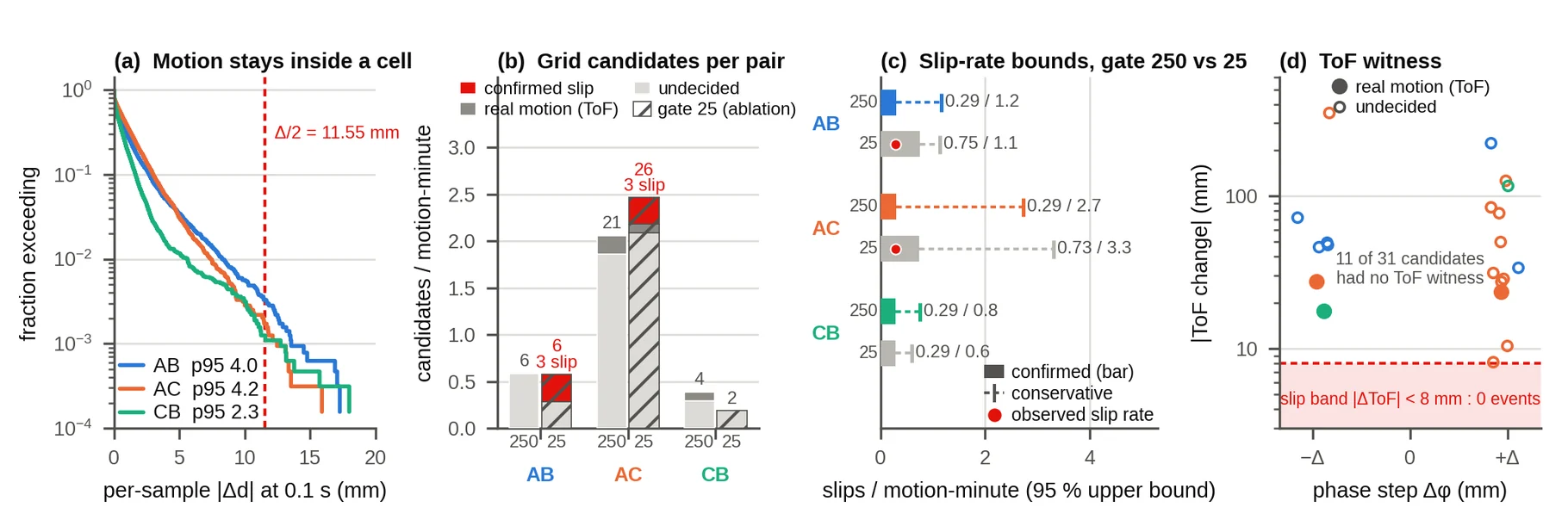
Over 22 freehand episodes — 30.7 pair-minutes of motion — the window detector raised 31 candidates, of which 20 carried a ToF witness: three were real motion and none fell in the slip band, so no slip was confirmed, with a one-sided 95% bound of 0.29 slips per pair-minute. The absorption gate is what buys this: lowering it from 250 to 25 mm/s produced six confirmed slips over a comparable 31.4 pair-minutes.
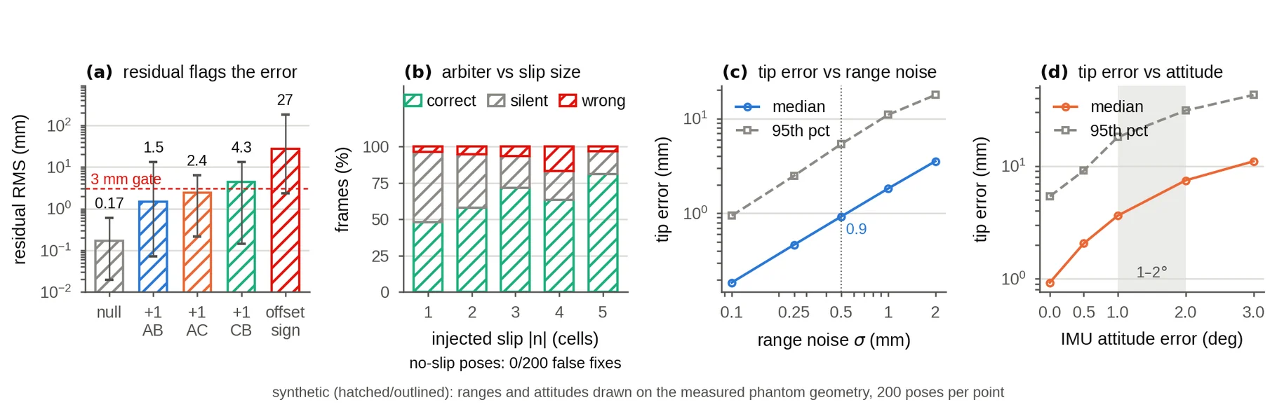
The spare equation behaves as a self-check. With everything correct the solve closed at a median residual RMS of 0.17 mm — the level of the range noise itself. An uncorrected one-cell slip raised it to 1.5, 2.4 and 4.3 mm depending on the pair, visible but often below the commit margin, which is why the arbiter stays silent on many single-cell slips. A wrong mounting-offset sign raised it to 26.9 mm, so a setup error of that kind cannot pass unnoticed.
Over 200 slip-free poses the ±5-cell hypothesis set committed no false fix. Over 200 injected slips it committed the correct correction in 126 (63%), stayed silent in 61 and picked a wrong cell in 13 — so 82% of its failures are silence rather than a wrong answer. With exact attitude, 0.5 mm range noise gives a median tip error of 0.92 mm; an IMU attitude error of 1° and 2° raises that to 3.6 and 7.4 mm, because the error enters through both the lever arm and the solved depth. Attitude, not range, sets tip accuracy, and that is where the next gain lies.
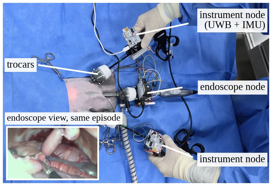
The logger was then carried into a live rabbit appendectomy with the same mounts and logging chain as in the phantom, and logged 11 episodes — 133 s of three-pair ranging and 6.0 pair-minutes of motion exposure — with the working ends inside the animal.
Limitations
In-vivo tip localization is not yet validated: those recordings need more episodes, and one instrument's IMU often produced incomplete attitude, so the records hold distances rather than solved tips. Ranging is relative — each episode is seeded by a ToF whose bias re-draws at every power cycle, so absolute accuracy against surveyed fiducials was not measured — and the integer is bounded rather than proven. The pivot is not perfectly fixed: the abdominal wall is viscoelastic, so a port that shifts during manipulation biases the solved depth. The nodes are development boards on 3D-printed mounts and need sterilizable packaging before clinical use, and the endoscope node is treated as fixed, so a moving endoscope would add a third insertion depth.