
Recording Hand-Held Laparoscopic Instrument Motion in the Operating Room: Magnetometer-Free Fusion of Inertial, Range and Visual Sensing
Most minimally invasive procedures are performed with hand-held instruments, yet only the endoscopic video is kept and the instrument motion is lost. A clip-on logger fuses a six-axis IMU and a time-of-flight rangefinder with a markerless camera in an error-state Kalman filter under the trocar’s remote centre of motion, with the shaft silhouette supplying heading in place of the magnetometer — whose field changed with tool pose and between sessions in our own measurements. Against a Franka Research 3, and without alignment to it, displacement error was 1.21 mm RMS over 300 trials and relative rotation 0.34° RMS over 180, with 1.22–3.04 mm absolute tip error on continuous trajectories tracked and displayed live.
A robotic system logs the kinematics of every case it performs. A hand-held laparoscopic instrument logs nothing — and hand-held is still how most minimally invasive surgery is done, with robotic use reaching only 15.1% across common general-surgery procedures by 2018 and 5.2% of Medicare cholecystectomies in 2019. What is lost is exactly the signal that skill assessment and imitation learning need: how the instrument actually moved.
The endoscopic video is the obvious place to look for it, but monocular pose estimates remain millimetres to centimetres off, worst along the viewing ray. So measure the motion on the instrument instead, with a module clipped to the handle side so that nothing entering the patient changes.
That plan has one immediate problem. An IMU gets heading about gravity only from its magnetometer, and on our own bench the magnetic field would not hold still.
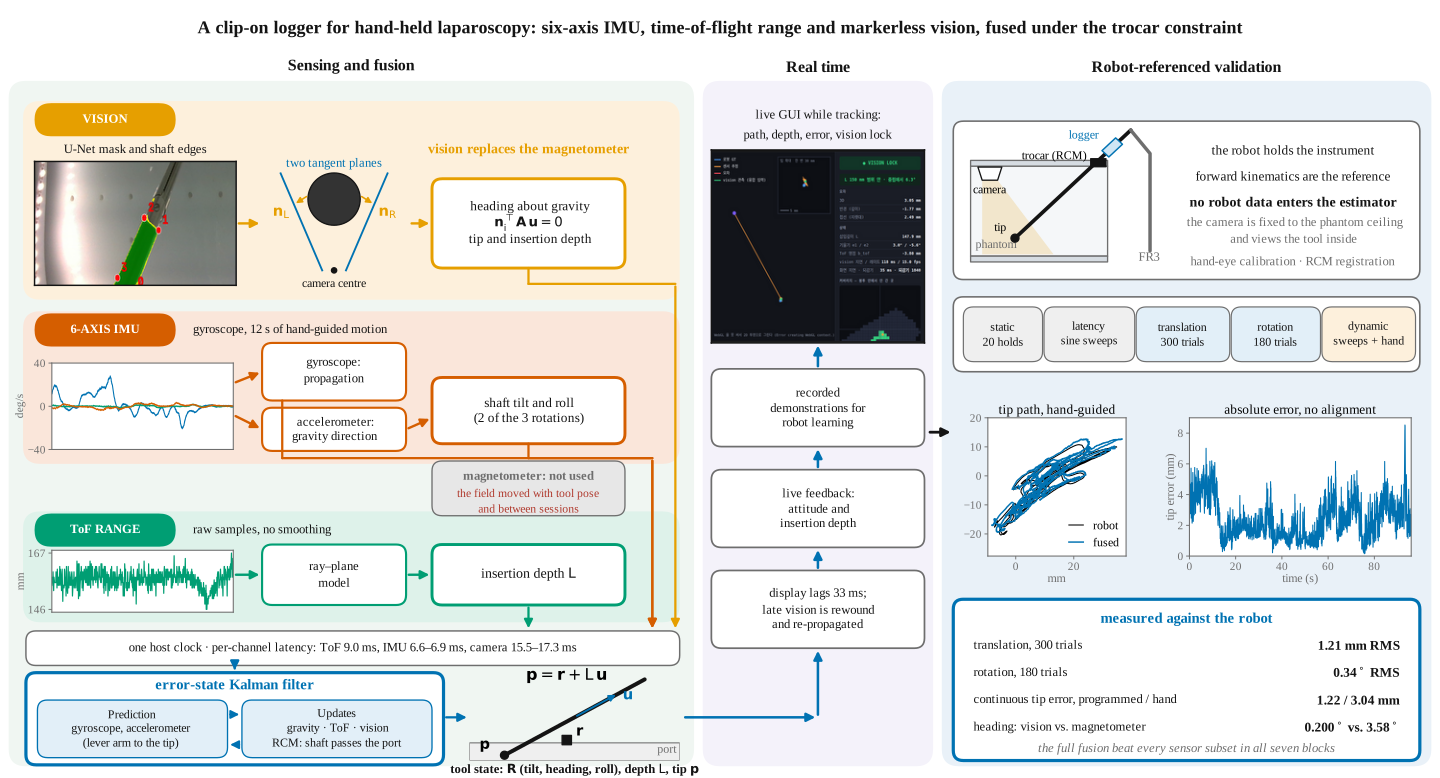
Why the magnetometer was removed, and what replaced it
Two measurements settled it before the main experiments.
Pose dependence. The Earth's field keeps a fixed angle to gravity. Across the 180 rotation trials that angle changed between the two poses of a single trial by up to 4.8°, against a 0.21° gravity residual. Rotation angles from the accelerometer and magnetometer alone erred by 3.58° RMS — eighteen times the error of the proposed fusion.
Session dependence. Between two static sessions recorded on one day the mean field fell by 21%, and the nine-axis heading drift within 30 s holds rose from at most 0.05° to 2.66°, while accelerometer tilt drifted at most 0.19°.
Neither is fixable by calibration, because heading uses only the horizontal component : a horizontal disturbance rotates the estimate by , so at µT a 5 µT disturbance already costs about 9.5°. Ten surgical facilities have measured 64 ± 20 µT on their operating tables against a ~35 µT background. Hard- and soft-iron calibration covers only material fixed to the sensor — not the table, and not the instruments being exchanged.
So the magnetometer is recorded and never used. Vision takes its place: gravity fixes tilt and roll, the shaft silhouette fixes heading, and a time-of-flight rangefinder fixes insertion depth, all fused under the remote centre of motion of the trocar.
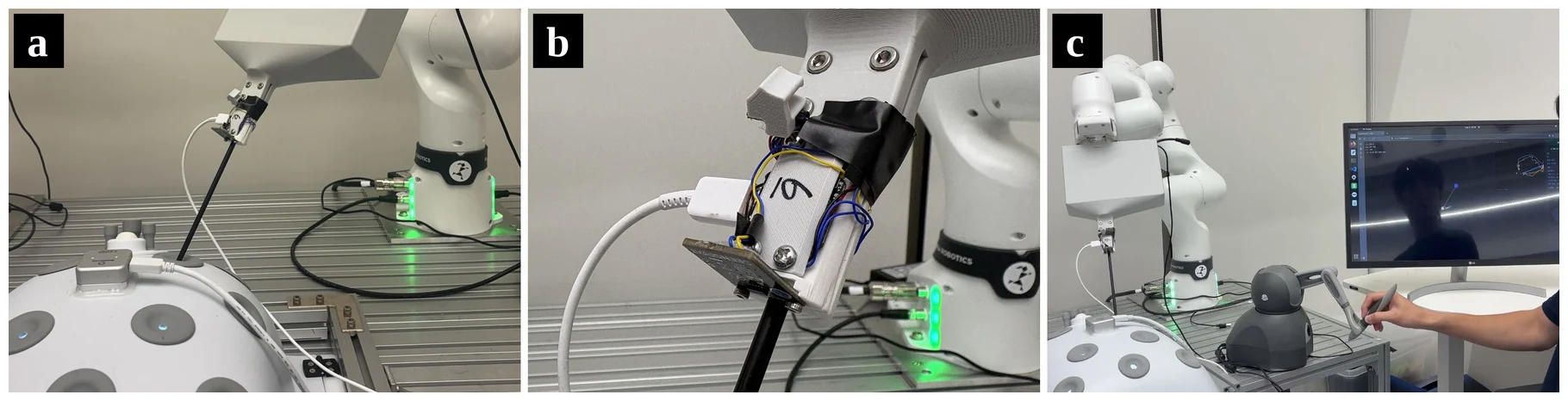
The module clamps to a standard 5.18 mm-shaft instrument and carries a BNO085 IMU, a VL53L0X rangefinder pointing distally toward the port, and an nRF52840 streaming gyroscope, accelerometer and raw range at 200, 240 and 100 Hz. A RealSense D405 above the phantom records 1280 × 720 at 15 fps. Every sample is stamped on arrival on one host clock.
| Sensor | Observes | Residual |
|---|---|---|
| Gyroscope | all three rotations; drifts, bias estimated online | 0.05 °/s bias |
| Accelerometer | shaft tilt and roll | 0.21° |
| Magnetometer | not used | — |
| Camera | heading; supports tilt, depth, lateral tip | 0.11°, 0.47 mm |
| ToF (raw) | insertion depth; weakly, orientation | 0.60 mm |
| Trocar (RCM) | tip across the shaft | 0.02–0.03 mm |
Because the trocar anchors the shaft line, the tip needs only the depth,
Getting heading out of a silhouette
The D405's stereo depth is valid on only 8.5% of the dark, smooth shaft pixels, so the geometry has to come from the colour image. A rule-based labeler puts each silhouette edge at the gradient maximum and fits a trimmed line — on 300 frames of one fixed pose its axis-angle scatter was 0.013°, against 0.409° for a human annotator — and its labels train a U-Net. At run time both run on every frame, and a frame reaches the filter only if the two masks agree to an IoU of 0.75 and their lines differ by less than 0.5° in direction.
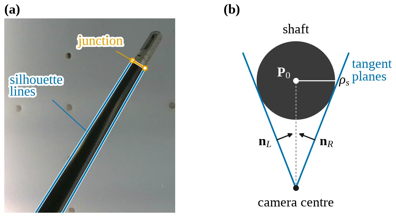
The obvious move — take the axis as — is ill-conditioned, because the two tangent planes are only about 3.6° apart, giving roughly 8° of error. Using the planes as constraints instead,
reduces the residual to 0.35° on the same data. The nearest axis point follows from the sum of the normals and is well conditioned.
The rangefinder gets the same treatment. An affine map assumes the beam looks along the shaft onto a surface normal to it; instead the beam is modelled with a fixed origin and direction on the tool hitting a plane fixed in the world,
The fitted beam turned out to be 55.8° off the shaft axis and the plane 13.4° off the neutral axis, so tilting in opposite directions changes the range in opposite senses — which a scale factor cannot represent, and absorbing it into one raises the tip error.
Every channel is late, and the filter is told by how much
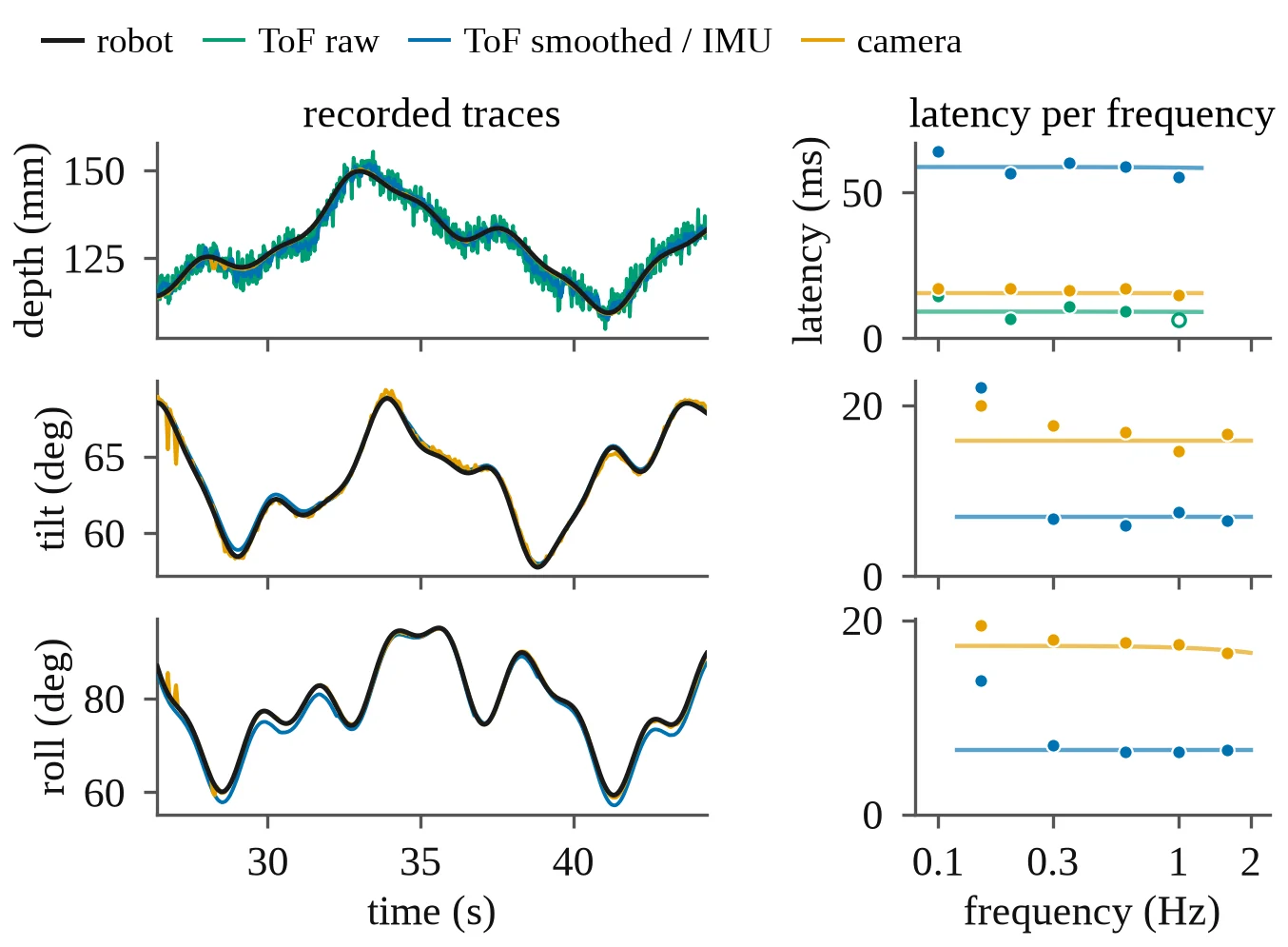
| Channel | ToF raw | ToF smoothed | IMU | Camera |
|---|---|---|---|---|
| Insertion depth | 9.0 ms | 58.7 ms | — | 15.5 ms |
| Shaft tilt | — | — | 6.9 ms | 15.8 ms |
| Roll | — | — | 6.6 ms | 17.3 ms |
The firmware's five-sample average costs 49 ms of extra delay and produces correlated samples a filter would count five times, so the display uses the smoothed depth and the filter uses the raw status-valid ranges.
The noise model follows the same principle of measuring rather than assuming. Accelerometer, ToF and vision errors proved to be dominated by pose-locked systematic components: the ToF depth scattered 0.43 mm over repetitions of one pose but 3.04 mm across poses. Treating those as independent per sample made the filter over-confident, so each σ is the held-out residual inflated by for correlated samples per pose.
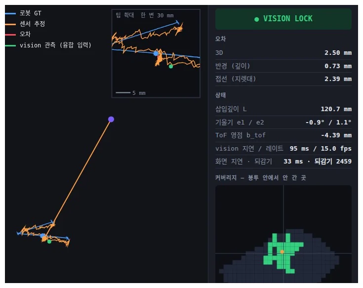
Segmentation and reconstruction take about 113 ms per frame, so the filter rewinds to the frame's capture time, applies the observation there and re-propagates — holding the estimate 30 ms behind real time instead of 113 ms, which the display reports as a 33 ms end-to-end lag. Once all inputs have arrived the live trajectory equals the offline causal filter, and the dynamic results use it without smoothing.
Measured against a robot, without aligning to it
Every experiment is referenced to an FR3 holding the instrument through the trocar, and no robot data enters the estimator. Robot ground truth is orders of magnitude finer than the errors measured (0.0001° rotation repeatability, under 2 µm of tip motion in pure roll).
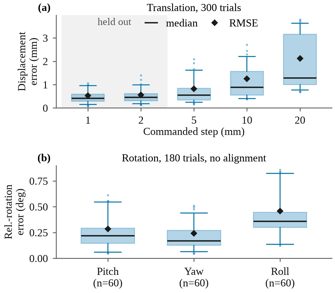
| Configuration | Translation RMSE (mm) | Scale | Rotation angle (°) | Rel. rotation (°) |
|---|---|---|---|---|
| Full fusion | 1.21 | 0.962 | 0.200 | 0.341 |
| No accelerometer update | 1.69 | 0.980 | 0.285 | 0.746 |
| No ToF | 5.97 | 0.749 | 0.198 | 0.340 |
| No vision | 12.65 | 0.955 | 1.087 | 39.4 |
| On-chip nine-axis fusion | — | — | 1.086 | — |
| Gyroscope integration | — | — | 1.170 | — |
300 translation trials and 180 rotation trials.
The ablations show the division of labour cleanly. Without vision the translation error grows tenfold and scales with distance, because nothing fixes heading — and in rotation the estimate ends up off by a 177° rotation about gravity, which is what "heading is unobservable" looks like in practice. Without ToF the direction survives but the scale collapses to 0.749. Without accelerometer updates an error floor appears even at the 1 mm step.
Against the same trials, the fused rotation-angle error of 0.200° is 5.4× lower than the BNO085's own nine-axis orientation and 5.9× lower than gyroscope integration.
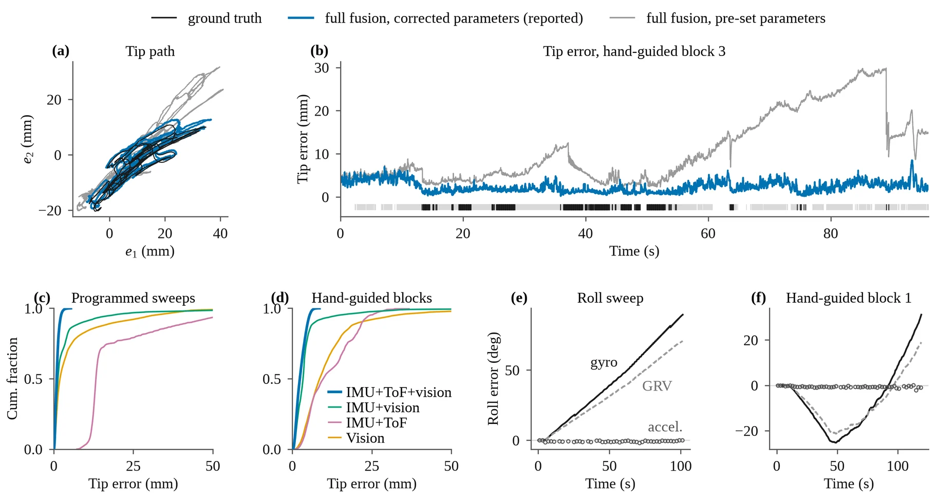
| Sensors (all with the RCM) | Programmed sweeps | Teleoperated |
|---|---|---|
| Vision | 13.36 mm | 27.52 mm |
| IMU + ToF | 23.36 mm | 13.93 mm |
| IMU + vision | 11.13 mm | 9.33 mm |
| IMU + ToF + vision | 1.22 mm | 3.04 mm |
Pooled RMSE of absolute tip error in the robot base frame, no alignment. The full fusion was the best combination in all seven blocks.
Vision alone reaches 13.4 and 27.5 mm because nothing bridges the frames it rejects — 64–78% of frames were accepted and only 14–44% passed the trocar gate. And when vision is deliberately degraded, by keeping one accepted frame in three, multiplying its axis noise fivefold and blanking it for 1, 3 and 10 s at sixteen points, the block-mean error rises only from 1.22 to at most 1.35 mm (programmed) and from 2.95 to at most 3.24 mm (teleoperated). Hiding the shaft junction alone, which removes the independent tip and freezes the ToF offset, is far worse: 6.2 and 7.7 mm.
The part that is honestly post-hoc
The parameters fixed before recording — the ones that drove the live display — gave 3.45 and 10.28 mm, almost entirely tangential. Integrating the gyroscope about the shaft against ground truth showed why: its bias moved during motion and accumulated 89° over the 102 s roll sweep, while accelerometer-derived roll stayed within 2.1°. The reported numbers re-run the same recordings with three cumulative changes.
| Parameters | Programmed RMSE | Teleoperated RMSE |
|---|---|---|
| Pre-set (live display) | 3.45 mm | 10.28 mm |
| + bias random walk ×10 | 3.16 mm | 13.35 mm |
| + vision tip offset | 1.24 mm | 13.35 mm |
| + gated-out tips | 1.22 mm | 3.04 mm |
The ladder is worth reading in order, because the middle rows get worse: loosening the bias lets the filter follow the drift but hands the position to vision, and only when the tip position of gated-out frames is restored does free motion come down to 3.04 mm. The third change is therefore not a refinement but a precondition — the loosened bias is safe only once vision constrains the position often enough. Since these were selected after inspecting the evaluation blocks, they remain to be confirmed on an independently recorded session.
What it is good for, and what it is not
The magnetometer is the only sensor here whose errors originate in the environment rather than in the device. Steel furniture and electrosurgical equipment affect neither gravity, nor the range to a surface, nor a shaft silhouette in an image — so an estimate with no magnetic quantity in it does not carry a bench calibration into a room that invalidates it.
Two consequences. A case could leave behind the metric tip trajectory that imitation learning needs, rather than a video from which pose must later be estimated — nothing is added inside the patient, no marker is placed, the camera already exists in the procedure, and no robot is involved. And because the estimate is causal, it is available during the operation: a surgeon cannot see insertion depth or attitude once the instrument is inside the patient, and the display supplies both at the gyroscope rate with a 30 ms lag.
The limits are as stated: one device on a phantom with a fixed ceiling camera, whereas an endoscope-mounted camera moves and adds its own pose; free trajectories were teleoperated rather than hand-held so that robot kinematics could serve as ground truth; monocular reconstruction was validated only near 140 mm insertion; the RCM is assumed fixed; and the labeler is tuned to one shaft appearance.